

Wiring microinverters with IQ Cable
The IQ Microinverter converts DC to AC, and the IQ Cable connects your IQ Microinverters in an AC daisy-chain.
Design and installation

This section guides you through designing and sizing an Enphase PV system, selecting compatible components, and wiring them correctly. You’ll also find step-by-step instructions for rooftop and electrical installation, covering all system configurations.
Thanks to our decentralised AC architecture with IQ Microinverters, panel placement is flexible.
Our Burst Mode technology ensures power generation even in winter months, cloudy conditions and low light.
No need to worry about shading or startup voltages.
Enphase IQ Microinverters are compatible with 99% of solar panels in the market.
Use our compatibility calculator to check. If your panel isn’t listed, you can manually enter the panel’s relevant specifications in the tool using the data sheet.
Match your panel’s nominal operating cell temperature (NOCT) value with the AC output of the microinverter. The NOCT value is a standardized metric that helps estimate the real-world performance of a solar panel.
For optimal performance, the panel’s NOCT value should be lower than the microinverter’s AC output. Below are two examples of a good match.
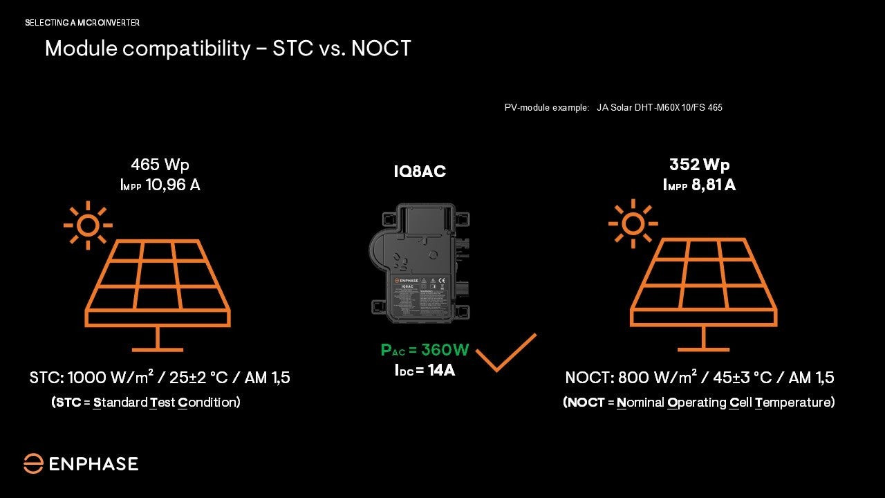
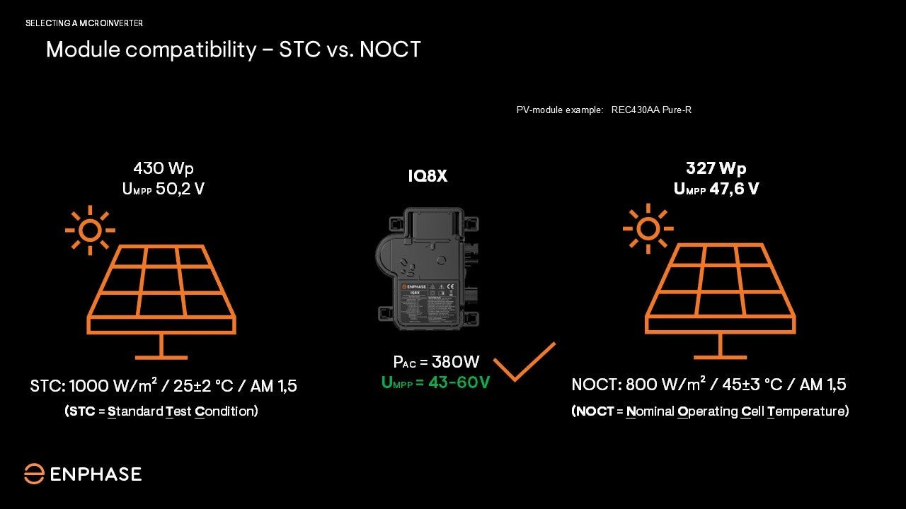
The IQ Microinverter converts DC to AC, and the IQ Cable connects your IQ Microinverters in an AC daisy-chain.
IQ Microinverters auto-assign to phases L1, L2, L3 during installation with the IQ Cable.
The number of IQ Microinverter per phase is limited. Please observe the electrical design specifications.
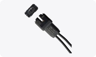
For a portrait orientation, choose the IQ Cable with SKU Q-25-17-3P-160
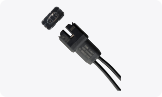
For a landscape orientation, choose the IQ Cable with SKU Q-25-20-3P-160
IQ Microinverters auto-assign to phase L1 during installation with the IQ Cable.
The number of IQ Microinverter at a single phase is limited. Please observe the electrical design specifications.
For a portrait orientation, choose the IQ Cable with SKU Q-25-17-240
For a landscape orientation, choose the IQ Cable with SKU Q-25-20-200
Rule 1
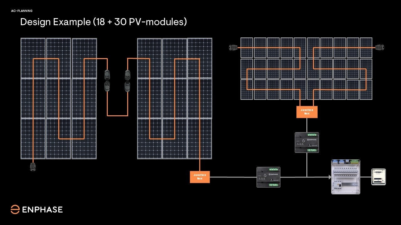
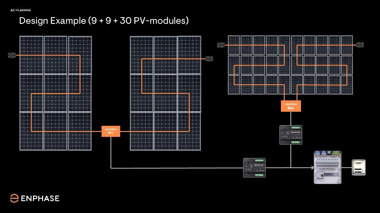
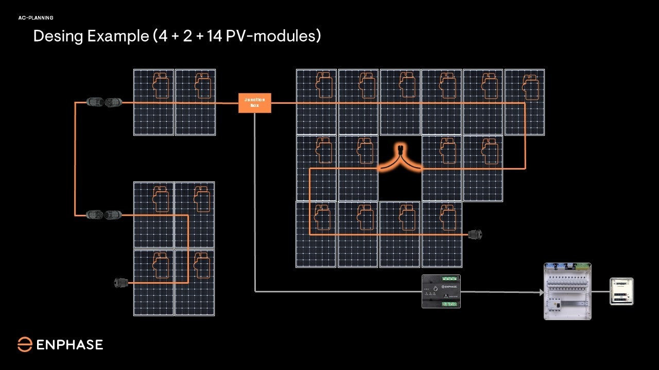
You can connect up to 18 IQ Microinverters using a continuous IQ Cable section in a three-phase system. This cable links the microinverters in the IQ Cable section.
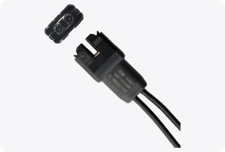
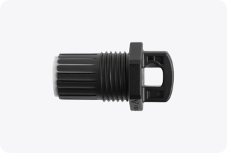
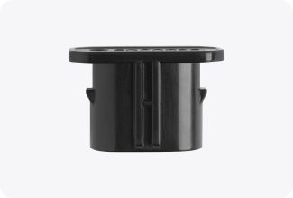
Each IQ Cable run starts with a Terminator Cap
Use Field-Wireable Connectors to bridge larger gaps
For small gaps (e.g. satellite dish), seal unused drops with a Sealing Cap
Use an IP67 certified junction box (third-party) to connect the IQ Cables to the homerun Cable
Make sure to plan for the correct amount of Terminator Caps, Field-Wireables, and Sealing Caps, based on the roof layout and panel arrays
Here are three examples of correct wiring with the IQ Cable:
Rule 2
The maximum number of microinverters per homerun cable depends on the specific microinverter model and system design.
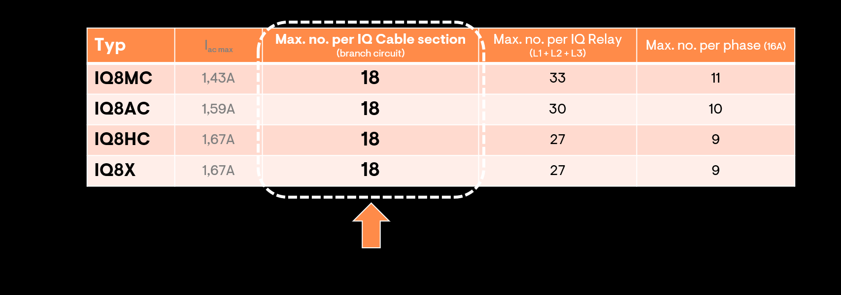
For example:
If you're using IQ8AC Microinverters with 27 solar panels, you can connect 18 microinverters on one IQ Cable and 9 on another. Then, join both sections at a T-piece junction box and run a single homerun cable from there.
If you're using IQ8AC Microinverters with 35 panels, split them across two IQ Cable sections (for example, 18 and 17 microinverters) and use two separate homerun cables.
Rule 3
The total cable length—from the distribution panel, through the homerun cable and IQ Cable, to the IQ Terminator Cap—should be no more than 50 to 70 metres.
Be sure to share this information with your design and roof teams.
Offer a complete energy solution tailored to your customer's needs.
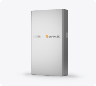
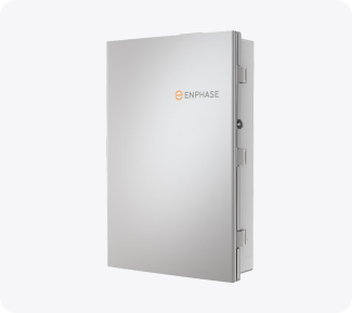
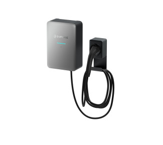
Reminder: Complete the mandatory certification courses at Enphase University for IQ Battery, IQ System Controller, and IQ Energy Router to ensure accurate technical planning.
Roof installations with Enphase are safe. No voltage is present in the system during installation.
Watch this video to see how it works.
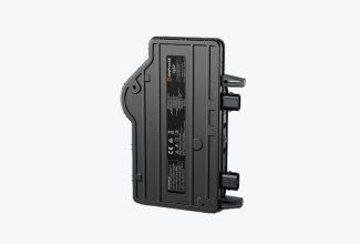
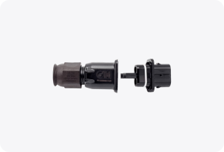
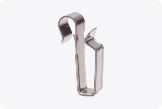
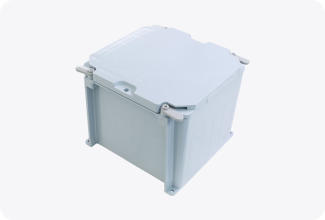
Use this checklist to ensure you're fully prepared for electrical installation before arriving on-site. Make sure you:
Downloaded and updated the Enphase Installer App
 |  |
Here is a quick overview of what you will be installing:
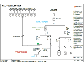
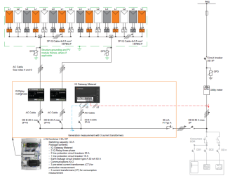
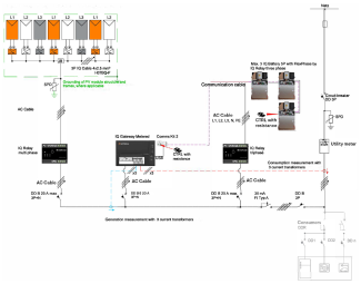
Install the Gateway.
Install a miniature circuit breaker before the Gateway.
Install the CTs (Current Transformers).
They measure production and household consumption.
Always follow these three rules:
• Arrow towards the IQ Gateway
• Match phases (L1 to L1, L2 to L2, L3 to L3)
• White over blue
Install a residual current circuit breaker type A 30 mA.
When the installation is complete, move on to commissioning.
The IQ System Controller enables seamless grid agnostic operation. Here is an overview of what you will be installing:
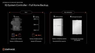
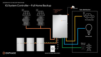
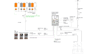
Install the IQ Battery. Certification from Enphase University is mandatory.
Install the IQ System Controller. Certification from Enphase University is mandatory.
You can add the Enphase IQ EV Charger 2 to any Enphase system.
You can integrate compatible EV chargers with the IQ Energy Router. Certification from Enphase University is mandatory.
View Quick Installation Guide
View compatible 3rd party EV chargers
Warning
There were previously products added in your cart. We have removed those products and added the BOM to your cart.
NOTE: IQ PowerPack 1500 supports maximum 400W solar input. Your cart has excess panels.

Installation address : , , ,
Installation address : Same as shipping address,
Warning
Installation services are available for a single installation site. If you'd like to get multiple EV chargers installed at different addresses, please complete a separate order for each address. To continue this order, please reduce the charger quantity or remove the install service from your cart.
Store sign in
Please enter your Enphase App credentials.
Back
Forgot your password?
Please enter your email address below to receive a password reset link.